Series and Parallel Circuits: How to Analyze Any Circuit in Physics
Two Ways to Connect Components
Every electrical circuit you will ever encounter, from the simplest flashlight to the most complex computer motherboard, is built from combinations of just two fundamental connection types: series and parallel. Everything else in circuit analysis, no matter how complicated it looks at first, is just these two patterns combined in different ways. Understanding the difference between them and what that difference means for current, voltage, and resistance is the single most important skill in basic electronics and electrical physics.
Series Circuits
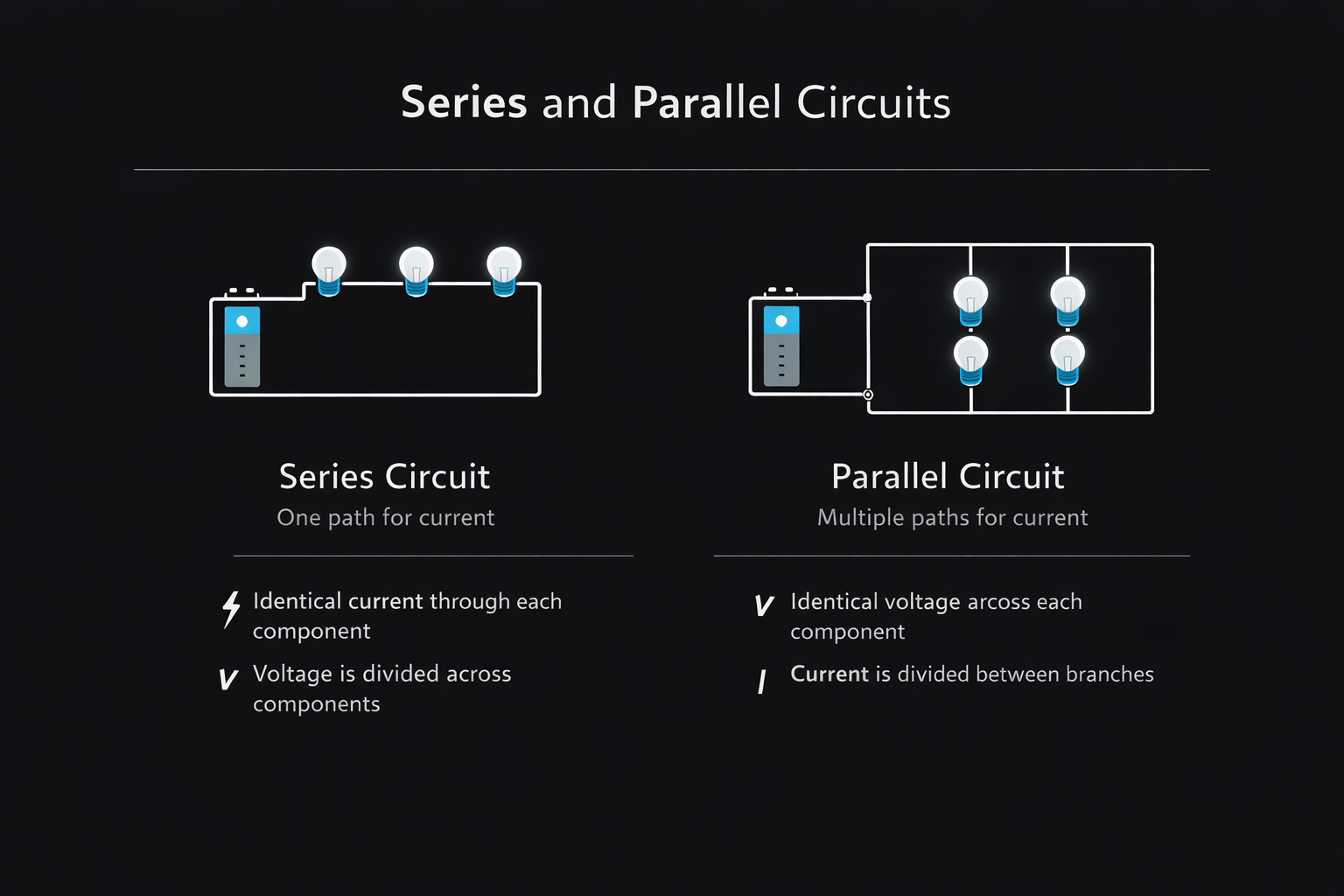
In a series circuit, components are connected end to end in a single continuous path. There is only one route for current to take, so it flows through every component one after another in sequence, like water flowing through a single pipe with no branches.
The key rules for series circuits are:
Current is the same everywhere. Since there is only one path, the same current flows through every single component in the circuit. There is no splitting or branching, so if you measure the current at any point in a series circuit, you will get the same reading.
Voltage divides. The total voltage supplied by the battery or power source is shared among all the components. Each component uses up some of the voltage proportional to its resistance. A component with higher resistance takes a larger share of the total voltage. This is called a voltage drop across each component.
Total resistance adds up. When resistors are connected in series, their resistances simply add together to give the total resistance of the circuit:
R total = R1 + R2 + R3 + …
So if you have three resistors of 2 ohms, 4 ohms, and 6 ohms connected in series, the total resistance is 12 ohms. Connect that combination to a 24V battery, and Ohm’s Law tells you the current is 24 divided by 12, which equals 2 amperes flowing through every component.
The voltage drop across each resistor can be found using Ohm’s Law individually. The 2 ohm resistor drops 2 x 2 = 4V. The 4 ohm resistor drops 2 x 4 = 8V. The 6 ohm resistor drops 2 x 6 = 12V. Add them up: 4 + 8 + 12 = 24V, which equals the supply voltage. This is always the case in a series circuit. The voltage drops across all components must add up to the total supply voltage. This rule is known as Kirchhoff’s Voltage Law.
The biggest weakness of series circuits is reliability. If any single component in a series circuit fails and breaks the path, the entire circuit stops working. This is exactly why old-style Christmas tree lights wired in series would go completely dark when a single bulb blew. Every bulb depended on every other bulb to complete the circuit. Modern Christmas lights are wired differently to avoid this problem.
Parallel Circuits
In a parallel circuit, components are connected side by side rather than end to end. Each component gets its own separate branch connecting the same two points in the circuit. Current has multiple paths available to it and splits among the branches.
The key rules for parallel circuits are:
Voltage is the same across every branch. Since all branches connect the same two points, every component in a parallel circuit sees the same voltage across it, equal to the supply voltage. This is fundamentally different from a series circuit, where voltage divides.
Current divides. The total current from the power supply is split among the parallel branches. How much current flows through each branch depends on the resistance of that branch. More current flows through lower resistance branches and less current flows through higher resistance branches. The total current entering a junction equals the total current leaving it. This rule is known as Kirchhoff’s Current Law.
Total resistance decreases. This surprises many students at first. Adding more resistors in parallel actually lowers the total resistance of the circuit. The reason is that each additional branch gives the current another path to flow through, making it easier overall for the current to pass. The formula for total resistance in parallel is:
1 / R total = 1 / R1 + 1 / R2 + 1 / R3 + …
For two resistors in parallel, there is a convenient shortcut formula:
R total = (R1 x R2) / (R1 + R2)
The total resistance of a parallel combination is always less than the smallest individual resistance in the group. Always. If you have a 4 ohm and a 6 ohm resistor in parallel, the total resistance is (4 x 6) / (4 + 6) = 24 / 10 = 2.4 ohms, which is less than either individual resistor.
The great advantage of parallel circuits over series circuits is independence. If one branch fails or is switched off, all the other branches continue to work normally because they each have their own complete path back to the power supply. This independence is exactly why parallel circuits are used for almost all practical wiring applications.
Series vs. Parallel: Complete Comparison
Current behavior: In series, the same current flows everywhere. In parallel, the current splits among branches.
Voltage behavior: In series, the voltage divides across components. In parallel, every branch gets the full supply voltage.
Total resistance: In series resistances, add up, making the total resistance larger. In parallel, the formula gives a total resistance smaller than any individual component.
Effect of one failure: In a series, the whole circuit stops if one component fails. In parallel, only that branch stops, and all others continue working.
Calculation approach: In series, add all resistances directly. In parallel, use the reciprocal formula or the product over sum shortcut for two resistors.
Common applications: Series circuits are used for current limiting, sensor circuits, and simple switches. Parallel circuits are used for home wiring, automotive electrical systems, and virtually all consumer electronics.
Worked Example: Mixed Circuit
Most real-world circuits combine both series and parallel connections. Here is how to approach a typical mixed circuit problem.
Suppose R1 = 6 ohms is connected in series with a parallel combination of R2 = 4 ohms and R3 = 12 ohms. The whole thing is connected to a 24V battery. Find the total current drawn from the battery and the current through each resistor.
Step 1: Find the equivalent resistance of the parallel combination of R2 and R3.
1 / R parallel = 1/4 + 1/12 = 3/12 + 1/12 = 4/12
R parallel = 12/4 = 3 ohms
Step 2: Now the circuit is simply R1 in series with R parallel. Add them:
R total = 6 + 3 = 9 ohms
Step 3: Find the total current from the battery using Ohm’s Law:
I total = V / R total = 24 / 9 = 2.67 amperes
Step 4: Find the voltage across the parallel section. Since R parallel = 3 ohms and I total = 2.67 A:
V parallel = 2.67 x 3 = 8 volts
Step 5: Find the current through each parallel branch. Both branches have 8V across them:
Current through R2 = 8 / 4 = 2 amperes
Current through R3 = 8 / 12 = 0.67 amperes
Check: 2 + 0.67 = 2.67 amperes, which equals the total current. Correct.
The strategy for any mixed circuit is always the same. Identify and simplify parallel groups first to find their equivalent resistance. Then treat those equivalents as single resistors in a series circuit. Apply Ohm’s Law step by step, working from total values down to individual components.
Why Home Wiring Uses Parallel Circuits
Every outlet, light fixture, and appliance in your home is wired in parallel with every other. This is not a coincidence. It is a deliberate engineering choice based on the properties of parallel circuits.
First, every device gets the full supply voltage, which is 120V in the United States and 230V in much of the world. Appliances are designed to operate at this specific voltage, so they need to receive it directly regardless of what else is plugged in.
Second, devices operate independently of each other. Turning off a lamp does not affect the refrigerator. Unplugging the television does not dim the lights. Each device has its own complete circuit back to the power supply.
Third, when a device fails, it does not take down the entire electrical system. A blown fuse or tripped circuit breaker in one branch only affects that branch.
The downside of parallel home wiring is that each device you add draws its own current from the supply. Add too many high-current appliances to one circuit and the total current exceeds the circuit breaker rating, causing it to trip. This is why you cannot run a microwave, a toaster, and an electric kettle from the same kitchen circuit at the same time without tripping the breaker.
Kirchhoff’s Laws: The Foundation of Circuit Analysis
For more complex circuits that cannot be simplified by series and parallel rules alone, physicists and engineers use two fundamental laws formulated by German physicist Gustav Kirchhoff in 1845.
Kirchhoff’s Current Law states that the total current entering any junction in a circuit equals the total current leaving that junction. Charge cannot accumulate at a junction, so whatever flows in must flow out.
Kirchhoff’s Voltage Law states that the sum of all voltage drops around any closed loop in a circuit equals zero. In other words, the total voltage provided by sources in a loop equals the total voltage dropped across all resistors in that loop.
These two laws, together with Ohm’s Law, give you everything you need to analyze any circuit, no matter how complex.
Frequently Asked Questions
What is the main difference between series and parallel circuits?
In a series circuit, there is only one path for current, so the same current flows through everything, and the voltage divides among the components. In a parallel circuit, there are multiple paths, so the full voltage appears across each branch, and the current divides among them.
Why does adding resistors in parallel decrease total resistance?
Each additional branch provides a current with another path through the circuit, making it easier overall for current to flow. The combined circuit conducts better than any single branch alone, which means lower total resistance.
How do you solve a mixed series and parallel circuit?
Always simplify parallel combinations into their equivalent resistance first, then treat the whole circuit as a series combination of those equivalents. Apply Ohm’s Law step by step from the total circuit down to individual components.
Are household appliances wired in series or parallel?
Parallel. Every outlet and appliance receives the same full supply voltage and operates completely independently of all other devices on the circuit.
What is Kirchhoff’s Voltage Law?
It states that the sum of all voltage drops around any closed loop in a circuit must equal zero. In practical terms, this means the voltage supplied by the battery or power source must equal the sum of all voltage drops across resistors and other components in that loop.
What happens if one component fails in a series circuit versus a parallel circuit?
In a series circuit, the whole circuit stops working because there is only one path and that path is now broken. In a parallel circuit, only the branch containing the failed component stops working while all other branches continue to operate normally.
Frequently Asked Questions
Get physics insights delivered weekly
Join students and educators receiving expert explanations, study tips, and platform updates every Thursday.
Join others. No spam.

allphysicsfundamentals
Making physics accessible, interactive, and genuinely understandable for students at every level.